|
|
 11-01-2010, 10:49 PM
|
#1 |
|
AstinaGT Regular

Join Date: Feb 2008
Location: Quakers Hill, NSW
Car: Mazda 3 & BA Astina
Posts: 277
|
ECU Wiring Diagram for BP-05 (BA Series 3)
Hi guys,
I finally got my car running, but I have major tuning issues trying to run my cams off the factory ECU. I've picked up a Greddy eManage to try and resolve the fuel delivery issues if possible. I've found a wiring diagram on Club323f.com that seems to match my ECU on the pins that I tested, but it's missing the wiring for the MAF and RPM pickup point that I need to get the basic unit up and running.  Does anyone have the full pinout listing of the ECU? |

|

|
| Sponsored Links |
|
|
|
11-01-2010, 11:11 PM
|
#2 |
|
HONEYWELL REPRESENT
 
Join Date: Aug 2005
Location: Salisbury - Inner City
Car: 1997 BA Hardtop - Had a 2003 BJii J48 Sport20, and 2x bg SOHC astina hatches
Posts: 5,011
 |
rupe, ryan, and cosmo dude will be the best people to ask about this buddy

__________________
|
|
|
|
|
11-01-2010, 11:27 PM
|
#3 |
|
Senior Member

Join Date: Sep 2004
Location: n/a
Car: n/a
Posts: 10,929
|
rpm pick up should be 11 or 12 on that diagram. comes off the dissy somewhere, as the CAS is located within the dissy itself, but i forget which.
11 is the wiring for the pulse that is sent up to the tacho in the dash. |
|
|
|
|
12-01-2010, 12:20 AM
|
#4 |
|
AstinaGT Regular
Join Date: Feb 2008
Location: Quakers Hill, NSW
Car: Mazda 3 & BA Astina
Posts: 277
|
Yeah I've now found the CAS as 4F and the Ignition signal under 4N after searching the US forums.
But still need this confirmed and MAF location. |
|
|
|
|
12-01-2010, 12:25 AM
|
#5 |
|
HONEYWELL REPRESENT
Join Date: Aug 2005
Location: Salisbury - Inner City
Car: 1997 BA Hardtop - Had a 2003 BJii J48 Sport20, and 2x bg SOHC astina hatches
Posts: 5,011
|
ok mate sorry 4 this stupid question. so ur looking 4 the oxgen sensor on the exhaust manifold??? it number 52. aka to get the air fuel ratio???
__________________
|
|
|
|
|
12-01-2010, 08:41 AM
|
#6 |
|
Senior Member

Join Date: Dec 2006
Location: Sutherland Sydney
Car: astina BA 1997 1.8Ltr
Posts: 609
|
the diagram you have there is for series 1/2. Series 3 is completely different. I've been searching for series 3 diagram for so long without any luck. I have all factory manuals including wiring diagram supplement but they all are written for series 1/2. Series 1/2 ECU has 3 plugs and series 3 has only 2 plugs. In series 3 ,MAF, IAT, TPS pins are all shifted from middle plug to left plug.
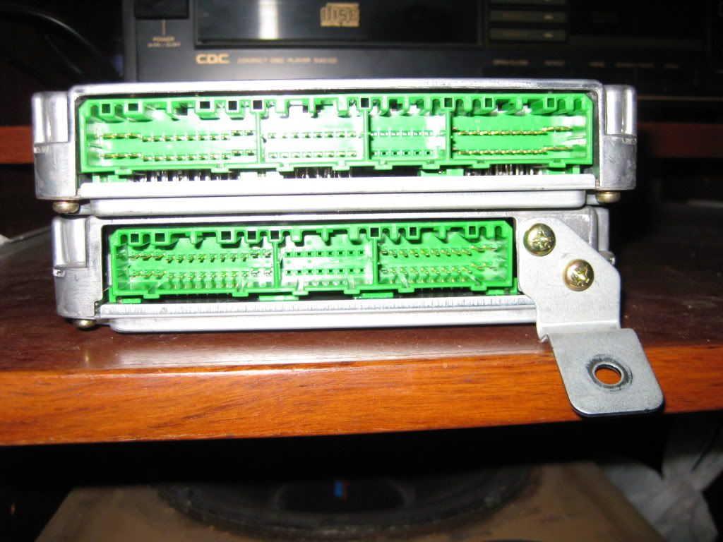 Top series 2, bottom series 3  If you go by the above pin diagram MAF wires are going to 4C=4A=4D (r/b), 4M (g/b), 4L (p), 4E, 4B(r/w) These 5 wires include IAT within them. 4C,4A, 4D are all interconnected. IAC wires 4Q (b/w), 4S (b) O2 sensor 4J TPS 4H (b/y), 4G (g/r) , 4E (b/b) in series 1/2 ECU these pins are used for different sensors or not used at all e.g 4E, 4H = crank position sensor (if available) 4G= not used 4S= not used 4Q= IAC valve
__________________
1997 Astina BA11P3, 5 Door Hatch, 1.8 DOHC, 5 Speed, 90,000 kms 
|
|
|
|
|
12-01-2010, 10:35 AM
|
#7 | |
|
AstinaGT Regular
Join Date: Feb 2008
Location: Quakers Hill, NSW
Car: Mazda 3 & BA Astina
Posts: 277
|
Quote:
Thanks Asanga! I'll give those a try. I saw your post elsewhere as well asking for the pinouts.... |
|
|
|
|
|
12-01-2010, 06:21 PM
|
#8 |
|
コスモ

Join Date: Dec 2002
Location: Location: Vic
Car: Mazda '95 Astina I4, '86 B2K and '10 3 MZR-CD
Posts: 7,888
|
The white wire from the distributor is tach signal, It looks like 4N is the ECU signal.
The only series 3 wiring manual I have is in Japaneese.
__________________
My 'stina Hatch |
|
|
|
|
12-01-2010, 06:34 PM
|
#9 |
|
コスモ
Join Date: Dec 2002
Location: Location: Vic
Car: Mazda '95 Astina I4, '86 B2K and '10 3 MZR-CD
Posts: 7,888
|
Looks like 4M is air volume and 4L is air temp.
If 4L is an output its input is common to one wire on the TPS and a water temp sensor. If I can get my scanner working I'll scan the JDM page which may help (and try labling things in english).
__________________
My 'stina Hatch |
|
|
|
|
12-01-2010, 09:07 PM
|
#10 |
|
AstinaGT Regular
Join Date: Feb 2008
Location: Quakers Hill, NSW
Car: Mazda 3 & BA Astina
Posts: 277
|
Yep I've been working through it today as well.....
This is what I've got working so far: 4M is the MAF single 4L is the Air intake temp sensor 4H is the TPS White wire from Dizzy is the RPM signal (currently pulling from Diagnosis connector) This has allowed me to get the basic functions of the eManage working - and tested! I'm currently working on the Injectors and Ignition at the moment. This is what I've found: 4U is Injector 1 4V is Injector 2 4W is Injector 3 4X is Injector 4 4C is Injector GND 4N is Ignition (Is this one correct as you had this as the ECU signal?) 4F is the Cam Angle Sensor (CAS)
__________________
2005 | Mazda 3 SP23 Hatch | Sunlight Silver [daily driver] 1997 | Mazda 323 Astina Hatch | Fridge White [soon to be daily driver] Last edited by SP BLING; 12-01-2010 at 09:09 PM. |
|
|
|
|
12-01-2010, 10:08 PM
|
#11 |
|
AstinaGT Regular
Join Date: Feb 2008
Location: Quakers Hill, NSW
Car: Mazda 3 & BA Astina
Posts: 277
|
Ok I've finished wiring the Injectors and Ignition as per the above and it works beautifully!
I've been able to add some additional timing in at idle and got it running relatively smooth now. Any idea where the Dizzy tach single comes out at inside the cabin? I'm guessing it's the signal in the cluster driving the Tacho?? |
|
|
|
|
13-01-2010, 12:22 PM
|
#12 |
|
コスモ
Join Date: Dec 2002
Location: Location: Vic
Car: Mazda '95 Astina I4, '86 B2K and '10 3 MZR-CD
Posts: 7,888
|
It comes through the engine harness and switches to the front harness in one of the three plugs between the ECU and firewall.
__________________
My 'stina Hatch |
|
|
|
|
19-01-2010, 05:07 PM
|
#13 |
|
AstinaGT Regular
Join Date: Feb 2008
Location: Quakers Hill, NSW
Car: Mazda 3 & BA Astina
Posts: 277
|
Thanks Cosmo! I found it behind the Instrument Cluster which is a little easier to access, so I tapped into it there.
Going for a Dyno Tune tomorrow so that will hopefully 100% prove if all the connections are working properly. |
|
|
|
|
20-01-2010, 01:34 PM
|
#14 |
|
AstinaGT Regular
Join Date: Feb 2008
Location: Quakers Hill, NSW
Car: Mazda 3 & BA Astina
Posts: 277
|
Well the ECU wiring is spot on. I'll post up a full ECU pinout chart shortly for the Series 3 for anyone else wishing to use an eManage or other piggyback.
Unfortunately for me, the eManage has not got enough fuel adjustment for my (non standard) engine.... So it's now gotta be replaced with a full standalone. |
|
|
|
|
20-01-2010, 01:40 PM
|
#15 | |
|
Senior Member
Join Date: Sep 2004
Location: n/a
Car: n/a
Posts: 10,929
|
Quote:
And what do you mean by the 2nd bit. Not enough adjustment to raise the amount of fuel injected in? |
|
|
|
|
|
20-01-2010, 02:16 PM
|
#16 |
|
AstinaGT Regular
Join Date: Feb 2008
Location: Quakers Hill, NSW
Car: Mazda 3 & BA Astina
Posts: 277
|
Yes - precisely that. I could possibly fit an adjustable fuel regulator to help increase the fuel pressure, but it's unknown if that'll still provide enough adjustment. Much easier to go for a full standalone.
Info from the tuner so far (yet to pick the car up):
|
|
|
|
|
20-01-2010, 02:38 PM
|
#17 |
|
Senior Member
Join Date: Sep 2004
Location: n/a
Car: n/a
Posts: 10,929
|
I thought the eManage controlled idle rpm?
|
|
|
|
|
20-01-2010, 09:13 PM
|
#18 | |
|
AstinaGT Regular
Join Date: Feb 2008
Location: Quakers Hill, NSW
Car: Mazda 3 & BA Astina
Posts: 277
|
Quote:
|
|
|
|
|
|
20-01-2010, 09:46 PM
|
#19 |
|
Junior Member
Join Date: Jul 2009
Location: New Zealand
Car: Mazda 323
Posts: 238
|
I have the diagrams for the 3 plug ECU if someone wants them PM me i might upload them
__________________
FE3 POWER
 1985 Mazda 323 BF5P - FE3T powered 1988 Mazda Familia BFMP XG-I FE3 Powered |
|
|
|
|
03-03-2011, 04:11 PM
|
#20 |
|
Senior Member
Join Date: Sep 2004
Location: n/a
Car: n/a
Posts: 10,929
|
Bump - someone got the pin outs for Series 3 ecu?
|
|
|
|
 |
|
|


 Linear Mode

